We present a part of the INCO-COPERNICUS technological research project IC15 CT 96-0742 SQUASH (For Standard-compliant Quality Control System for High-level Ceramic Material manufacturing, see [3]). The project has been in progress since 1997. The aim of the project is to develop a non-contact system for automated quality inspection of industrially produced objects, in particular ferrite cores, magnets, and ceramic materials. Such products are used, among others, in measuring devices, and their quality is essential for assuring the required precision. An inspection system should be able to detect dimensional, surface and inner (sub-surface) defects that can greatly affect the quality of a product.
The SQUASH
project serves as a contribution to the standards of IEC
(International Electrotechnical Commission) for quality assessment
of ferrite cores and to the standardisation schemata
of the quality system ISO 9000![]() IEC-Q.
Producers expect an increase of reliability by
decreasing the classification error rate by 50%
with respect to the currently used manual quality control.
IEC-Q.
Producers expect an increase of reliability by
decreasing the classification error rate by 50%
with respect to the currently used manual quality control.
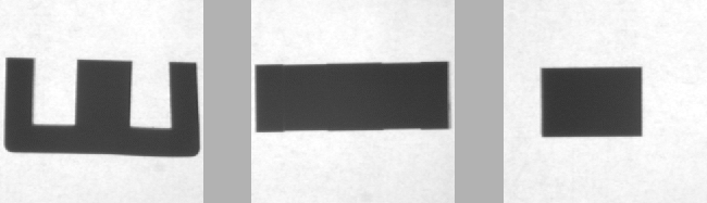
The main defects to be detected and measured are surface and sub-surface cracks, roughness of surfaces and shape defects such as missing parts, chips, bending, deflection or dimension inconsistencies. In order to detect these defects two types of sensors are used: optical sensors and electromagnetic (EM) sensors. The optical system is suitable for detection of surface and shape defects. Special illumination is applied to enhance such defects as surface roughness and cracks, as illustrated in figure 1. The sub-surface defects are detected using an EM sensor. The surface and sub-surface inspection parts of the SQUASH project are described elsewhere [3].
 |
Here, we present the methods developed and used for detection, measurement and classification of shape defects. The current practice of production control is to select sample objects produced and measure their dimensions with a mechanical gauge that either accepts or rejects an object. Also, the distributions of the dimensional measurements are obtained to monitor the production parameters. To comply with this practice, an optical shape gauge system was developed in order to quickly reject the obviously defective products and then measure the smaller but still critical dimensional deviations from the standard values specified by the producer. The original version of the system [6] was developed in an earlier project. This version has limitations that are discussed in section 3.3.
The standard and the acceptable values of the dimensions refer to the basic views of an ideal product. We will use E-cores, a particular sort of ferrite cores, to illustrate operation of the shape defect detection system. An example of E-core is shown in figure 2.
The assumptions and the goals of shape measurement and defect detection are as follows. Given a particular object with the specified dimensions and acceptable deviations, consider the characteristic views at the stable positions of the object. This results in several 2D shapes whose dimensions should be measured, gauged and classified. The pose (position and orientation) of the shape is arbitrary. Only a single shape is present in the image. The shape is completely visible and does not touch the borders. For geometrical correction and calibration, four reference points forming a rectangle are shown in the corners. Under these conditions, the system should:
The overall check and rejection are necessary because one can readily discard the definitely defective samples. For such samples, measuring the individual deviations makes no sense as these deviations either fall beyond the measurement range or cannot be defined at all.
The shape gauge system handles arbitrarily oriented projections. The comparison of the measured and the reference shape is therefore shift- and rotation-invariant. To determine the orientation of an arbitrary shape, a rotation-invariant shape matching approach should used.
We present a general matching methodology and algorithms for shape defect detection. Section 2 discusses the specifics of the general shape defect defection problem and states the problem on formalized level. The matching methodology, which is based on the notion of the Hausdorff distance, is presented in section 3. Tests are described in section 4, while section 5 discusses potential extension to direct three-dimensional measurements.
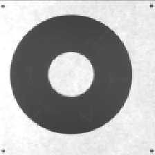
In section 6 we present another system. This system measures the critical dimensions of circular magnet rings with subpixel accuracy. This system does not require shape matching, because the measurements are direct, not relative to a reference, as discussed in section 3.3. A example of a circular magnet ring is shown in figure 3. (The small circles in the corners are calibration markers.)
Finally, the experience we gained in the course of the SQUASH project is discussed in section 7. We comment on several important questions related to the optical shape gauge, including its potential and limits.